Control Systems in Kerbal Space Program
Posted to site: 04/10/18
Drone and quadcopter usage is at an all time high, but controlling them isn’t exactly plain sailing. In a theoretical setting, applying equal power to each motor should cause the vessel to rise straight up. In practice, with inevitable discrepancies in design and manufacture, producing such a perfectly symmetric system is impossible. So the question arises, how can we vary the speeds of each motor to stabilise and control the aircraft? Such questions are normally answered in an environment such as MATLAB with Simulink but the video game Kerbal Space Program and addon kRPC provide a fun sandbox in which to experiment.
The setup
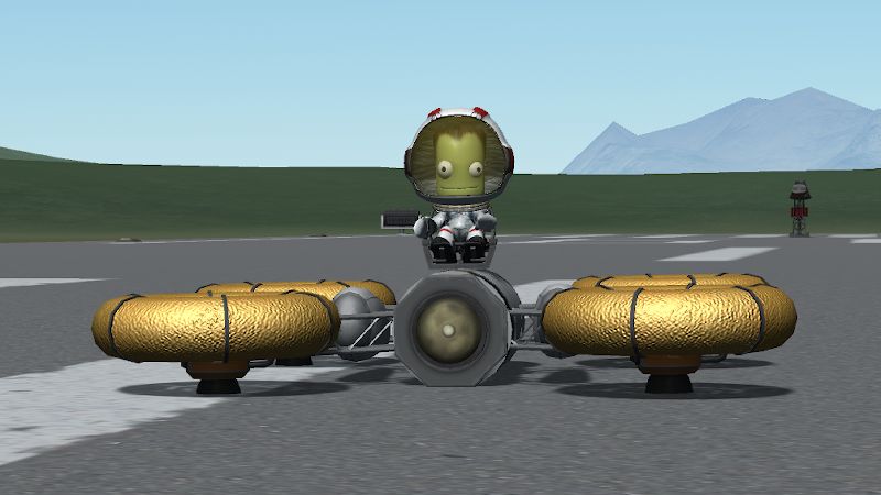
The goal of this project was to design, build and attempt to control a rudimentary “quadcopter” in the video game Kerbal Space Program. To be in with the best chance, the vessel should satisfy a few design requirements. Firstly, the craft should be as symmetric and balanced as possible; more precisely, the centre of mass and centre of thrust should be as close as possible so that the craft doesn’t flip over straight away. Secondly, we need the engines to be highly responsive to change in thrust because we will be constantly altering them to keep the craft flying level. In Kerbal Space Program, this means sticking with liquid rocket engines such as the 48-7S “Spark”. Note, we don’t need any engine gimballing because we will steer the craft by varying the thrust across the 4 engines.
For the design I will be using, please see Figure 1. This design has one considerable drawback over a conventional quadcopter, in that there is no way to control the yaw of the craft. This will be discussed more later, but controlling this axis shouldn’t be necessary to achieve stable flight. Moreover, it should be possible to maneuver the craft in 3D space without having any control of the yaw axis (although it will be pointing in a random direction).
Next, we need some way of measuring the current state of the vessel, processing that information somehow, and then adjusting the thrust on each engine accordingly. There are two competing methods for achieving this goal, namely the two mods kRPC and kOS. kOS is arguably simpler to implement but all scripts must be written in its custom programming language. Conversely, kRPC allows you to write your scripts in C++, Java, Python or many other languages. In this project, I will be using kRPC with Python.
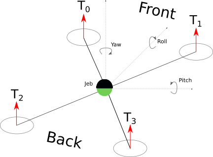
Figure 2 defines the basic model of the quadcopter that we will be flying, including the numbering of the engines 0 through 3 and the definitions of pitch, roll and yaw.
Control systems
The basic problem presented is how to control the thrust of each engine \( T_i \) over time in order to achieve some desired state (normally referred to as the set state). In this case, for simplicity, we aim for a set state with both zero pitch and roll, and altitude at a fixed height. In a noisy system finding an analytic solution to this problem is impossible, there are simply too many variables which cannot be accurately measured or predicted. The solution must therefore be reactive; the system will have to be constantly measuring the state of the vessel and making adjustments accordingly. As shown in Figure 3, we must design a controller which accepts our set state and the current state and adjusts the engines accordingly.

How do we design such a controller? A first idea would be a proportional controller; the current error in the system is multiplied by some predefined constant (or gain) and the output is the control signal sent to the engines. Denoting the current error as \( e(t) = x_* - x(t) \) where \(x_*\) is the desired set state, we can express the control signal outputted to the engines as \[c(t) := k_p e(t)\] for some given gain \( k_p \). To test out this idea, I did a quick test in MATLAB. To simplify the problem, we reduce to a 1 dimensional system; a point which starts at \( x = 5 \) and is aiming for state \( x = 0 \). At each time step the state is updated and then the acceleration of the point is set to the control signal of the proportional controller plus an “air resistance” term. Click here to download the m-file I used to model this control system.
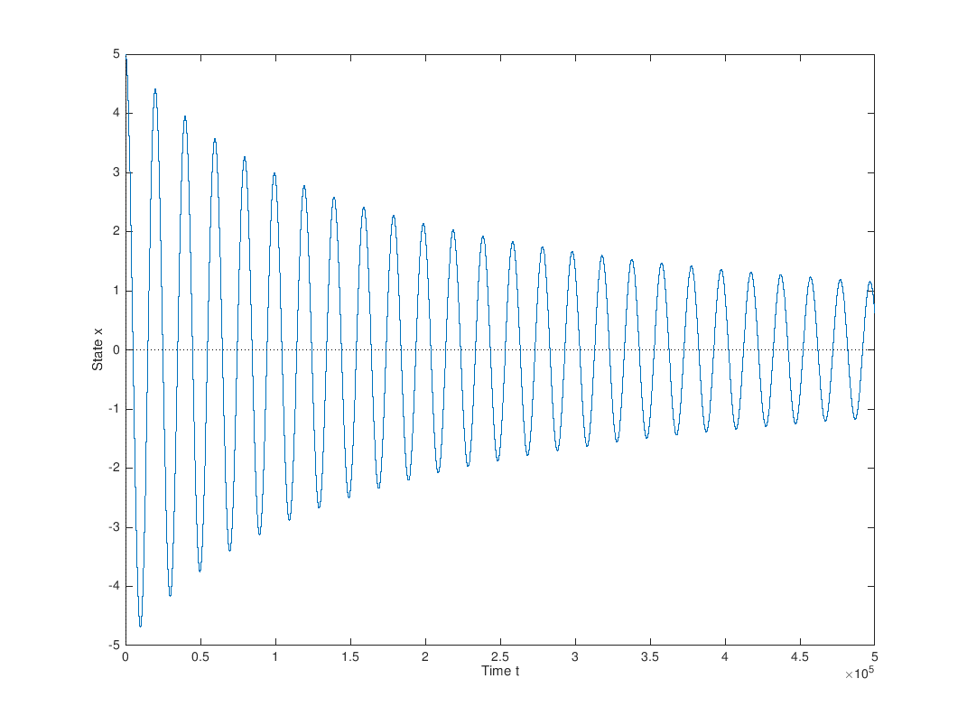
Figure 4 shows how this system evolves over time; there is a clear issue. The controller is only aware of the current error in the system so it keeps wildly overshooting the set state and the point ends up oscillating around the set state. The reduction of the amplitude of these oscillations is due only to the damping in the system from air resistance. After finely tuning the gain, a proportional controller might be acceptable in some applications, but it would make for a very nauseating flight for Jeb and may even shake the craft apart.
PID control
A PID control system aims to remedy the issue with the proportional controller demonstrated above. The name of this control system represents its constituent parts; the proportional, integral and derivative terms. The PID control system can be expressed mathematically as
\[c(t) := k_p,e(t) + k_i \int_0^t e(x);dx + k_d \frac{de(t)}{dt} \]
where \(e(t)\) is the error at time \(t\), \(c(t)\) is the output control signal at time \(t\), and \(k_p\), \(k_i\) and \(k_d\) are the proportional, integral and derivative gains respectively. Note, the proportional term of this system is identical to before, this term deals with the current error in the system. The next term is the integral term. Intuitively, this term adds up all previous errors in the system and so represents past error. The final term is the derivative term which calculates how quickly the error is changing. This term is very important because it is the only term which predicts the future. It can be viewed as the braking term because it will reduce the acceleration as the system approaches it desired state.
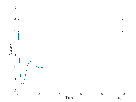
We can model this controller in a similar way to the proportional controller, to see how they compare. Viewing the simulation in Figure 5, we clearly see that the PID controller is doing a much better job. The system has settled down into the set state in under 2 oscillations, and before time \(t = 4 \times 10^4\), whereas the proportional controller was still oscillating around the set state with a large amplitude at time \(t = 5 \times 10^5 \). Click here to download the m-file I used to model this control system.
PID controllers are featured in many modern drones across numerous applications and thus it was the natural choice. For this project we will only need 3 PID controllers, one for pitch, one for roll and one for altitude, but real drones would also include a PID controller for yaw. The next question to answer is how these control signals should be combined to control the engines. Note if we wish to increase the altitude of our craft we should increase the power of all engines. To increase the roll of our craft we should increase \(T_0\) and \(T_2\) while decreasing \(T_1\) and \(T_3\). Finally, to increase the pitch of our craft we should increase \(T_0\) and \(T_1\) while decreasing \(T_2\) and \(T_3\). This gives us the following powers for each of the engines:
\[ \begin{align} T_0 &= -c_{pitch}(t) - c_{roll}(t) - c_{alt}(t),\\T_1 &= -c_{pitch}(t) + c_{roll}(t) - c_{alt}(t),\\T_2 &= +c_{pitch}(t) - c_{roll}(t) - c_{alt}(t),\\T_3 &= +c_{pitch}(t) + c_{roll}(t) - c_{alt}(t). \end{align} \]
The final problem is how to tune the gains \(k_p\), \(k_i\) and \(k_d\) for each of the controllers. In the world of quadcopters the PID tuning of your craft is a very personal choice and reflects how responsive or smooth you want the vessel to be. There is not necessarily a correct tuning for a given craft let alone across all craft. There are plenty of good resources online that guide you through the process of tuning these gains. Likewise, there are plenty of competing algorithms (including using a genetic algorithm) for automatically tuning PID controllers with various different goals in mind.
Working example
This system has one problem which became apparent fairly quickly in testing. The problem arises if you release the drone at a great height (say 5km) and ask it to achieve a low altitude (say 100m). Now, the difference between the drone’s target altitude and actual altitude is massive so \(c_{alt}(t)\) becomes very large and negative. This has the effect of drowning out the pitch and roll control signals so the engines will not fire at all. Consequently, the drone will tumble out of the sky out of control which may be impossible to recover from, resulting in catastrophic failure. The solution was to clamp \(c_{alt}(t)\) between -0.8 and 0.8 to keep the signal from becoming overwhelming.
If you would like to download the Python file which controls the quadcopter in Kerbal Space Program please click here. To use this script you will need to have Python installed locally and the kRPC mod installed in your instance of KSP. Also, so that the script can properly detect the engines, you will need to set an initial thrust limiter on the engines where engine \(T_i\) has a thrust limiter of \(i/10\).
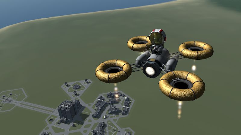
Figure 6 shows a demonstration of the PID loop. First Jeb gets launched upwards with all engines firing equally, and natural asymmetry in the craft causes the quadcopter to start pitching down. Then we activate the PID controllers and the flight levels out, settling at an altitude of 100m. By setting the target altitude to ground level (approximately 35m here) we can land Jeb safely back on the ground. Throughout this video you can see the thrust limiters of each engine being automatically adjusted by the control system to keep the craft at the set state. Note I have set the derivative gain on the altitude loop rather high (2.0) because overshooting the altitude on a descent could prove fatal.
Next steps
So far, all this system is capable of is maintaining a given pitch, roll and altitude. It would be possible to control these 3 variables manually to maneuver the vessel but, especially without yaw control, it would be challenging. Ideally, we would like to be able to give the controller a point in 3D space which it would navigate to autonomously. This is another program which is difficult to solve analytically and so could potentially solved by another PID loop. This new system would calculate the vector to the target position and feed this into a PID loop, producing the new set state for the pitch, roll and altitude which would then be achieved by another PID loop. Such a system is called cascade control. Moreover, as the control system is based on a feedback loop, the target point need not be stationary so the drone could be programmed to chase a target vehicle.
In Kerbal Space Program, a PID control system could be used to execute a powered descent in order to safely bring a rocket first stage back to the ground, similarly to SpaceX’s Falcon 9 series of rockets. A cascade control system could also be used to guide the rocket back to the initial launchpad or another safe landing site. Although, how to do this in the most fuel-efficient way (which is crucial for lowering the costs of a reusable launch system) is more of a question for optimal control theory.
Another possible extension to this project would be to use the accelerometer in a mobile device as an input device for the set state so that the quadcopter would mimic the orientation of the device. kRPC opens a server for interacting with the game which can be accessible on the entire network, so this control system could run entirely as a self-contained application on the mobile device. Although, this may incur latency issues depending on the speed of the network.
Another direction for this project would be to explore different control systems. One such system to explore could be the linear-quadratic regulator (LQR). An LQR seeks to minimise a quadratic cost function subject to a system of linear differential equations. The difficulty in designing such a system is properly defining the cost function and is usually an iterative process, similar to tuning a PID controller.
In Kerbal Space Program it’s probably safe to assume that the telemetry readings are accurate but in the real world we are not blessed with such reliable sensors. A Kalman filter takes the readings from the sensors and combines that information with a model for the craft to provide a “best guess” as to the actual orientation and position of the craft. This allows the control system to filter out noise from unreliable sensors and provide a much more stable flight which isn’t as reactive to random noise in the system.